Jet pump installations require precise handling of downhole equipment, tubing paths, and surface circulation systems. These pumps are designed to operate in both normal-flow and reverse-flow configurations, offering flexibility for wells with varying production profiles, tubing constraints, or surface facility layouts. The installation process involves staged preparation, controlled deployment of the bottom-hole assembly, and verification of surface flow paths before startup.
Normal-Flow Downhole Configuration
In the layout of the pump assembly in its standard circulation mode key components include:
- Jet pump Bottom-Hole assembly
- On/off tool (optional)
- Production packer
- Standing Valve
- Jet Pump
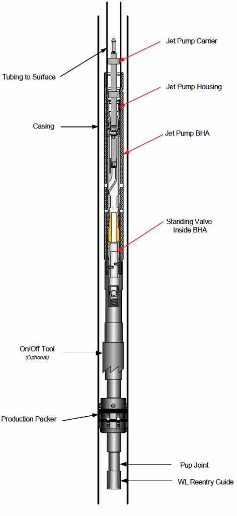
In this configuration, power fluid is pumped down the tubing, energizes the jet pump, and returns with produced fluids up the casing.
Normal-Flow Installation Procedure
- Run the BHA, packer and optional on/off tool
Pipe doped only on pin connections to keep inside of tubing clean. Confirm Tubing drift I.D. - Prepare or install a standing valve
The standing valve is dropped down tubing and pumped into position inside the BHA. Circulation continues until clean fluid returns up the casing. - Pressure-test the system
Casing, Standing Valve, On/Off tool, and Packer are pressured to a target value while and is monitored for stability. The guide notes a typical test to around 1000 psi. - Install surface wellhead equipment
Once the wellbore is tested, the workover rig is removed, and the wellhead is configured for jet pump operations. - Set the jet pump
- Circulate a minimum of 1x tubing volume.
- Drop Jet Pump.
- Pump down tubing until Jet Pump seats inside the BHA.
- Adjust surface pump speed
Injection pressure is raised to the planned operating point, then fluid returns are checked to confirm net production gains.
Reverse-Flow Downhole Configuration
Some wells require reversing the direction of power fluid and return flow.
In this arrangement:
- Power fluid is pumped down the casing.
- Produced and power fluid returns flow back up the tubing.
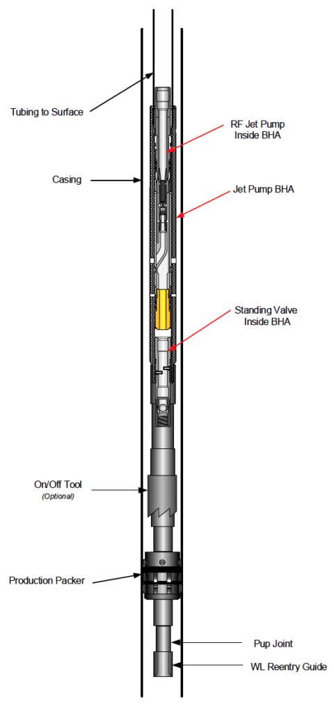
This configuration improves performance in wells where annular flow paths are preferred for solids, gas handling, or pressure behavior.
Reverse-Flow Installation Procedure
- Run the BHA, packer and optional on/off tool
Same drift ID limitations apply. - Install the standing valve
Dropped into tubing and seated inside the BHA, followed by circulation until clean fluid returns up the casing. - Pressure-test the well
Tubing is pressured to the expected operating range, then monitored for ten minutes via the casing side. - Configure the wellhead for reverse flow
Surface lines are arranged so that injection is routed down casing while returns flow up tubing. - Set the pump
The reverse-flow jet pump is run in hole using a slick-line running tool and latched inside the BHA. - Begin circulation and adjust RPM
Injection pressure is increased until the system reaches its target operating point. Return volumes must indicate net production.
Power Fluid Source: Fluid Vessel or Stock Tanks
A Jet Pump System needs a continuous source of “Power Fluid” to power the Jet Pump. This fluid is typically stored in either a pressurized vessel or existing stock tanks on location. Each system has different benefits, and some drawbacks.
Power Fluid Vessel
- Easy to confirm jet pump is producing
- “Closed loop” system reduces chance of dissolved oxygen
- Production separator only deals with “produced fluid”
- Can be used in more remote locations
Stock Tanks
- No gas entrainment in Power Fluid
- Solids can settle out in stock tanks
- Production separator must separate Power Fluid and Produced Fluid
- Oxygen can be introduced into the system
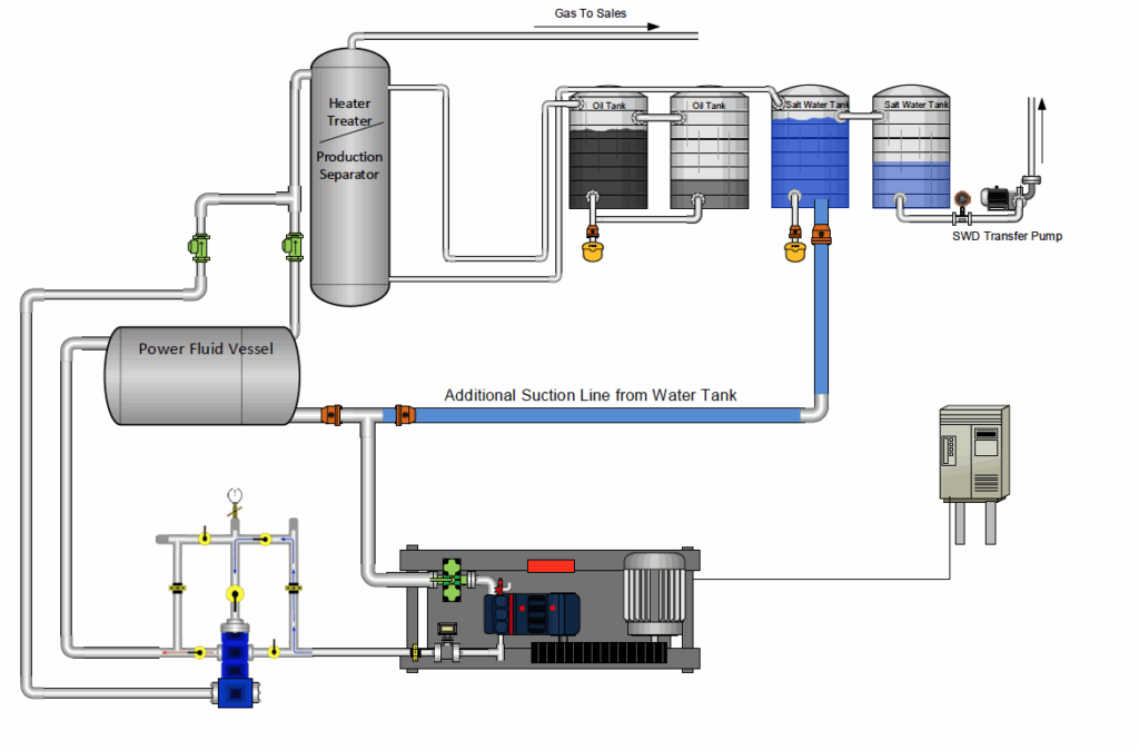
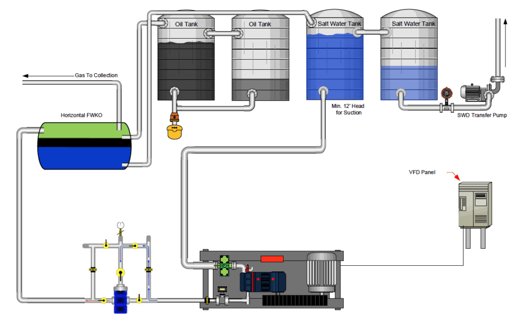
These layouts emphasize clean power fluid circulation, stable suction conditions and correct tank arrangements.
Reliable Operation Through Correct Setup
Proper installation and verification drive the performance of a 2.5-inch jet pump system. Ensuring pressure integrity, using the correct tools, seating the pump accurately and arranging surface lines for the chosen flow direction all contribute to steady production once the pump is activated.
This size range is widely used due to its versatility and compatibility with various well conditions, and both normal and reverse flow provide options for tailored lift performance.