Reverse-flow jet pump systems offer a flexible way to lift fluids in wells where conventional circulation paths or flow geometries create operational constraints. This configuration redirects the return path of power fluid and produced fluids, allowing the pump to function effectively in wells with unique inflow profiles, solids concerns, or packer limitations. The installation process requires careful preparation, testing and verification of both tubing and casing integrity before the pump is set.
Preparing the Well for Installation
Reverse-flow systems rely on proper pressure integrity across the tubing, casing and packer. Before any downhole equipment is run, both tubing-set and non-tubing-set configurations must be pressure tested.
A plug and prong assembly is run and pressure tested to the desired value.
- Pressure is held for ten minutes to confirm stability.
- The plug and prong are removed before proceeding.
This establishes a verified pressure envelope for the equipment that will follow.
Installing the Standing Valve
The standing valve can be installed in two ways:
- Dropping the valve from surface into the wellhead, allowing it to fall into place while pumping fluid down tubing.
- Running the valve on a dedicated tool, seated directly in the designated nipple profile.
Both methods aim to fill the wellbore with clean fluid and ensure the valve is properly landed before moving to the next steps.
Once installed, the casing, standing valve, packer and associated components are pressure tested. The document specifies pumping down the casing until fluid returns up the tubing, followed by holding pressure at 3000 psi for ten minutes to confirm integrity.
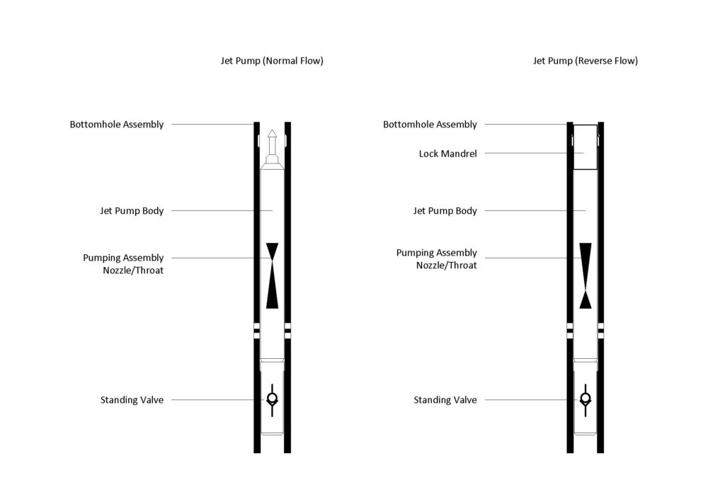
Running the Reverse-Flow Jet Pump Assembly
The pump assembly is deployed using a locking mandrel designed to engage with the downhole profile. The assembly includes:
- A jet pump section built for reverse-flow operation
- A nipple profile sized for the standing valve
- A check valve
- A pup joint to space the assembly correctly
- A locking mandrel to secure the pump in position
Once the assembly is set and locked, the mandrel is sheared, and the running tool is removed.
Understanding the Reverse-Flow Path
In normal flow, power fluid is injected down tubing and returns up the casing. In reverse flow, the injection and return paths are swapped.
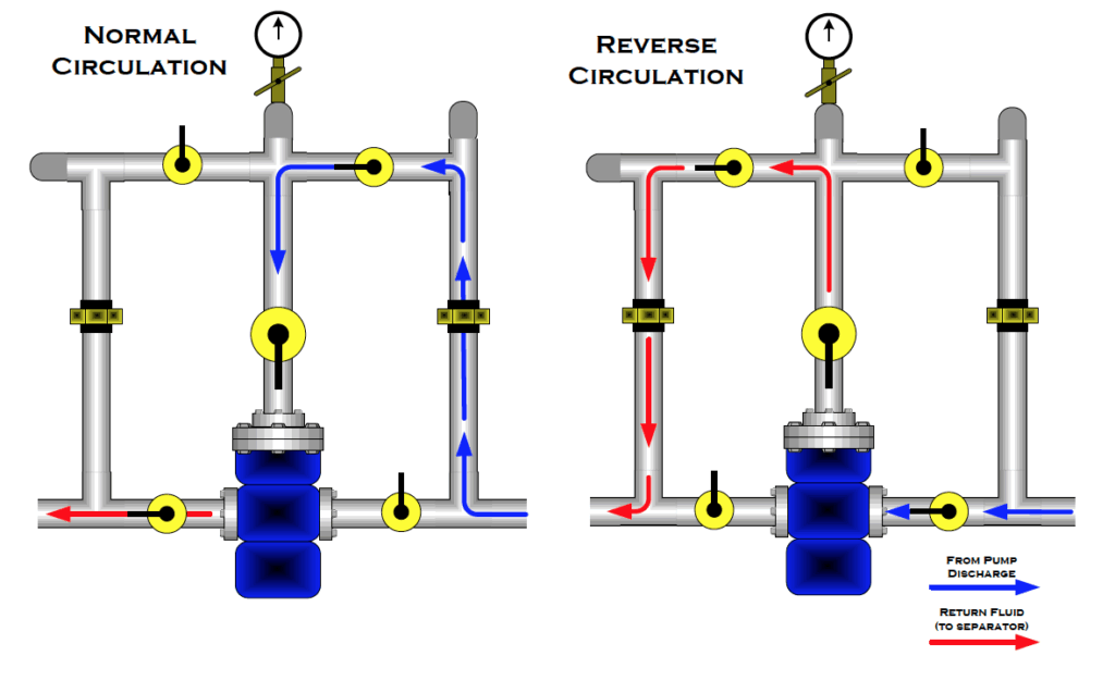
This configuration is useful when:
- Tubing ID limits the return flow path
- Casing flow provides more stable pressure behavior
- The operator wants to manage solids more effectively in the larger annular path
- Equipment layout at surface favors one circulation direction over the other
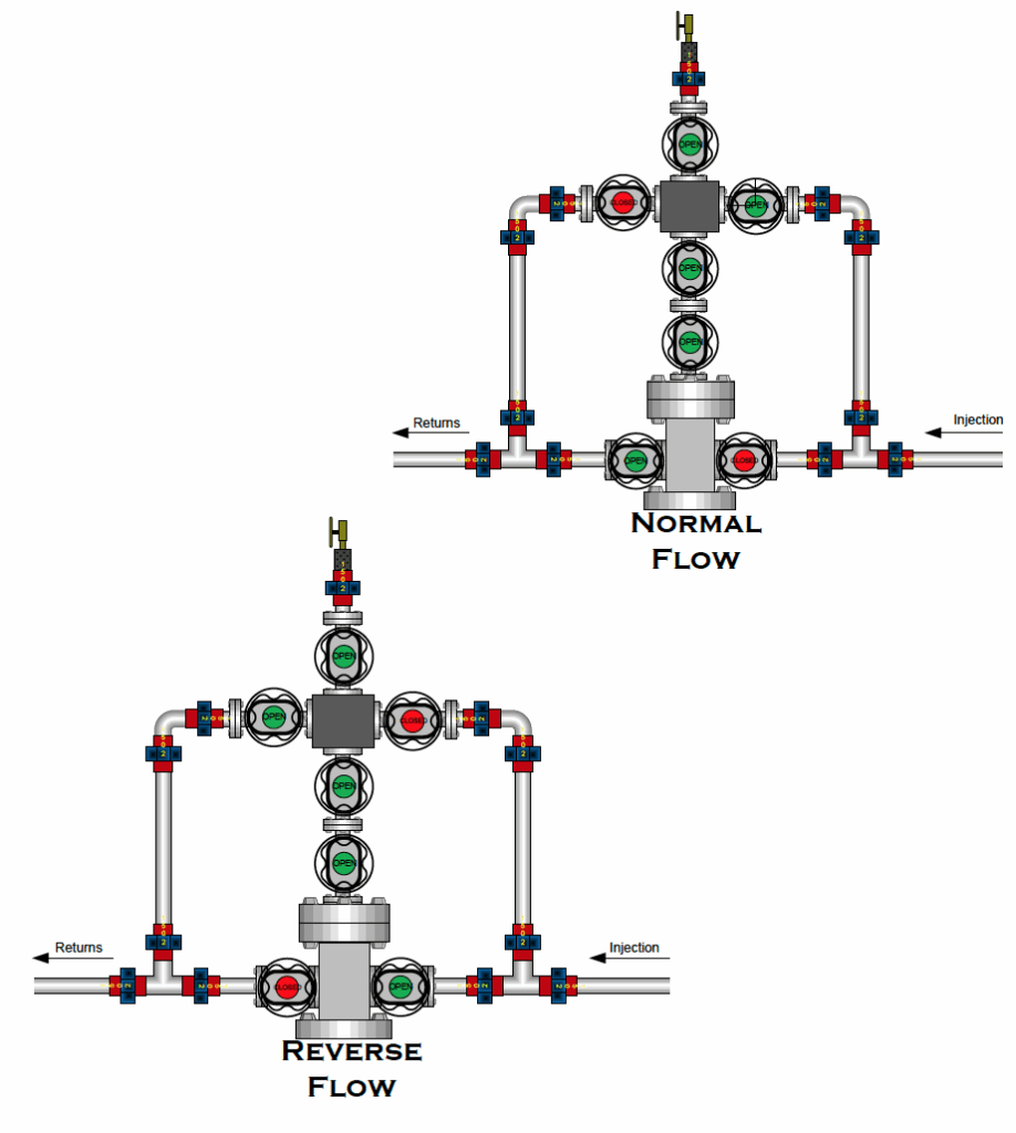
The diagrams show how valves are adjusted to switch between circulation modes, making the system adaptable during installation, startup and troubleshooting.
Surface System Layout
The standard components used with a reverse-flow system includ:
- A power fluid vessel
- A high-pressure surface pump
- Pump suction lines
- Return lines to separation equipment
- Tubing and casing lines designated for each flow direction
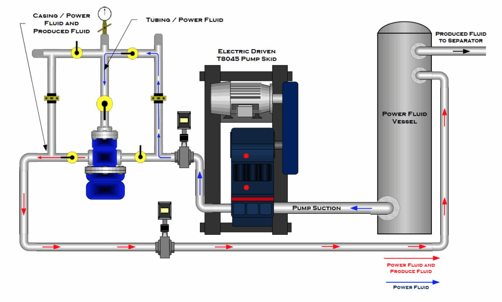
In this setup:
- Power fluid is drawn from the vessel
- Pressurized fluid enters the well to energize the jet pump
- Produced and power fluid return to the surface for separation
- Cleaned fluid is recirculated through the pump
Proper identification of injection and return lines is critical, especially when switching between normal and reverse flow.
Downhole Pump Geometry
The components of the downhole pump include:
- Internal fishneck
- Lock profile
- Upper and lower packing mandrels
- No-go shoulder
- Seal bore
- Return channels designed for the selected flow direction
Each packing element must be sized precisely to maintain seal integrity and prevent cross-flow between sections of the pump.
Key Considerations for Reliable Operation
Reverse-flow jet pumps rely on accurate installation and strict adherence to pressure testing requirements. Field personnel should verify:
- Proper seating of all downhole components
- Correct orientation of circulation valves at surface
- Adequate fill of the wellbore before pump startup
- Clean power fluid with minimal solids
- Tightness of all seals and packers
- Proper engagement of the locking mandrel
When installed correctly, reverse-flow systems offer strong flexibility and can operate effectively in wells where standard circulation paths are impractical.