Proper jet pump sizing depends on understanding how pump geometry, well conditions and surface constraints interact. Fortunately, we have Jet Pump design software to better predict the nozzle and throat combination that delivers the required production rate while staying within pressure, horsepower and cavitation limits. The process relies on systematic inputs and a comparison of multiple pump configurations to find a balanced operating point.
1. Input Data Establishes the Operating Envelope
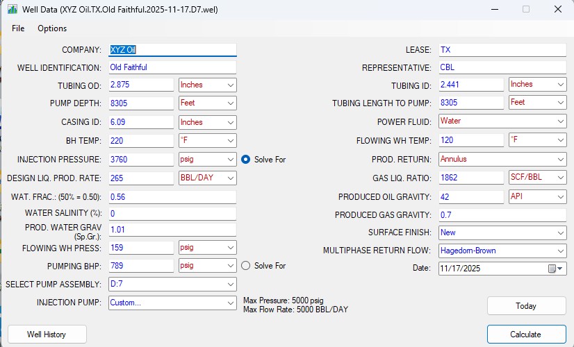
The first step is entering well and surface conditions. These values define the physical limits the pump must work within. Key inputs include:
- Tubing and casing dimensions
- Bottomhole Pressure/Temperature (Static and Dynamic)
- Produced Fluid Gravities
- Water/Oil Ratio, Gas/Liquid Ratio
- Surface pumping capabilities
- Collection facility location (Tank Battery/Flowline)
These parameters allow the sizing tool to calculate pressure losses, required horsepower and the feasible range of nozzle and throat combinations.
2. Generating Pump Configurations
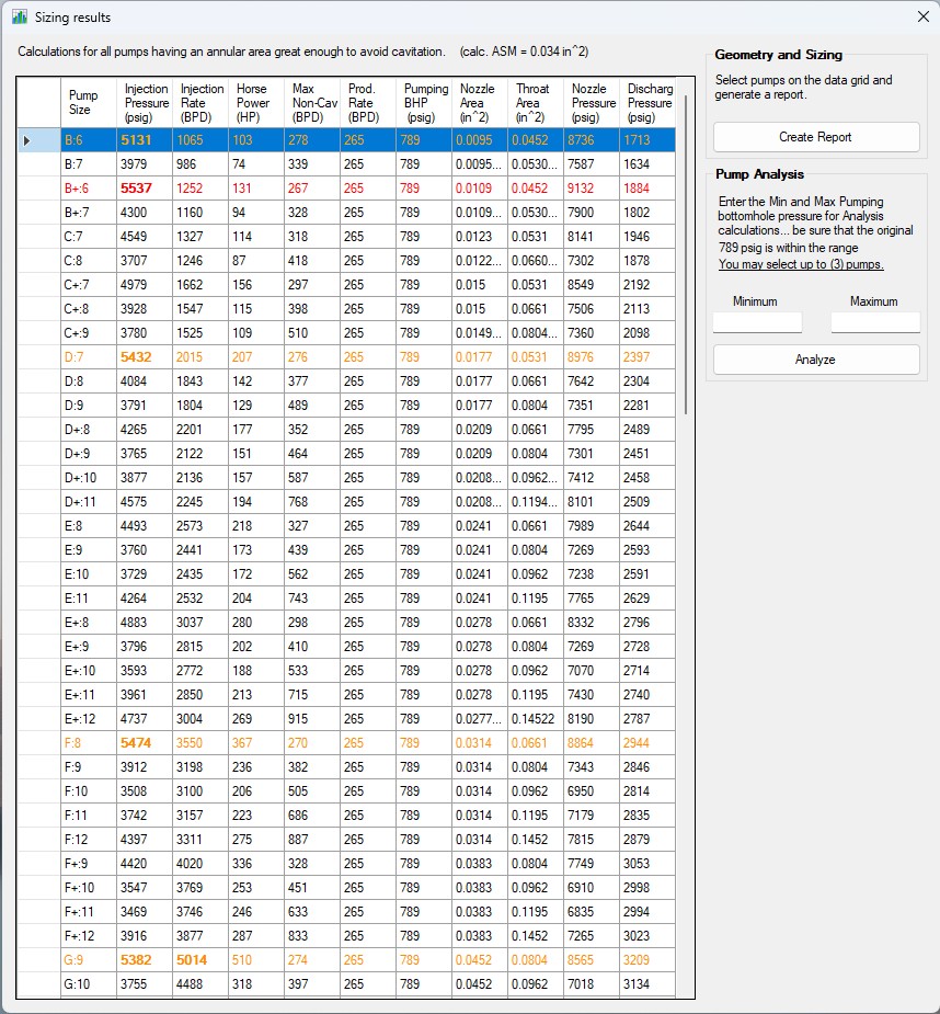
Once input data is set, the Jet Pump software/app calculates all pump sizes that meet the minimum criteria for operation at a given production rate.
Each calculated result includes:
- Nozzle / Throat size
- Injection pressure
- Injection rate
- Maximum non-cavitation production rate
- Fluid Horsepower Required
This full list of configurations lets engineers compare pump designs in a controlled, side-by-side format.
3. Cavitation and Intake Pressure Checks
Avoiding cavitation is central to reliable operation. The sizing calculations identify the best operating conditions to operate outside the cavitation limit. Configurations that fall within the cavitation threshold are removed from consideration.
Production rate, injection pressure and especially pump depth play a direct role as the Jet Pump draws down the reservoir pressure. The correct combination of nozzle and throat must provide drawdown without violating cavitation limits.
4. Matching Production Goals with Available Injection Pressure
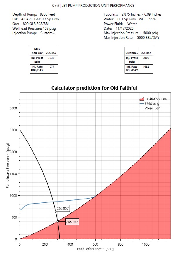
After filtering out unstable options, the engineer compares performance curves. These curves show:
- Pump intake pressure vs. production rate
- The effect of injection pressure at different production levels
- The intersection with the inflow curve (often the Vogel relationship)
The optimal pump sits at the point where intake pressure predicted by the pump matches the inflow from the reservoir while staying within the available injection pressure at surface.
5. Selecting the Best Pump for the Well
The final selection for a target production rate accounts for:
- Injection pressure
- Produced Gas volumes
- Horsepower (Kw)
- Surface System Constraints
A well-designed jet pump system can meet a production target while avoiding any surface or downhole constraints that could increase downtime and/or limit production.
6. Performance Verification
Once the pump is chosen, a performance plot confirms the operating point. The graph typically overlays:
- Cavitation boundary
- Jet Pump intake pressure for a given injection pressure
- IPR Curve or Productivity Index Line
The intersection defines the expected steady-state production rate. This visual check ensures that the pump is properly matched to the reservoir conditions and surface capabilities.
A Systematic Approach Produces Reliable Results
By integrating geometry, surface system constraints, fluid properties and pump configurations into a structured comparison workflow, engineers can choose a jet pump that fits the well’s conditions and the operator’s production goals. The structured sizing process strengthens confidence in the optimal selection and supports reliable, long-term operation.